|
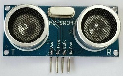
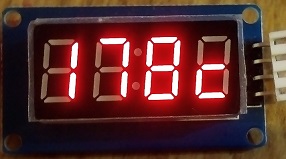
DISTANCE METER HC-SR04 ULTRASOUND SENSOR
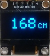
Using PIC12F629 and PIC16F628A each drives OLED display and TM1637 4 digits 7 segment LED display.
OLED SSD1306 0.96" screen is driven by software I2C.
With TM1637 LED brightness can be set in the code, value can be 0-7.
The sensor is triggered once every 500mSec. The recomended range is 0.1 to 3 metres.
When switching power on with the link fitted the reading changes to inches. With TM1637 the right digits displays c for cm or i for inch.
Accuracy changes up to 2% depending on air temperature that affect the speed of sound and the frequency of the PIC internal oscillator.
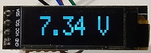
OLED 10V VOLTMETER ATtiny13/25/45/85
OLED display, 128x64, 0.96", SSD1306, I2C or 0.91" 128x32. OLED is driven by software (bit banging) I2C.
The sketch and circuit can be used without any changes for ATtiny13/25/45/85
ATtiny13 can be programmed using Arduino IDE and Arduino as ISP. Use these instructions https://www.electronics-lab.com with the setting : 9.6MHz, no millis no tone, LTO enabled.
10K resistors can be carbon film as long as they are next to each other so resistance drifts the same in temperature, otherwise use metal film resistors.
ATtiny85 can be programmed using Arduino IDE and Arduino as ISP, see Technical Tips Burning bootloader with setting "Clock Source 8MHz internal", "LTO enabled".
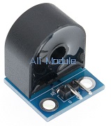
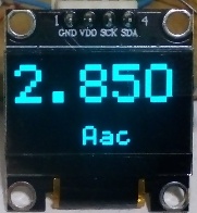
OLED AC CURRENT METER
OLED display, 128x64, 0.96", SSD1306, I2C with PIC12F675. OLED is driven by software (bit banging) I2C. Code includes functions for reading the sensor. Moving the decimal point can be done in software only.
R is calculated for 5V drop at max AC current, R = 5 / I secondary. Trim 10K pot to desired reading. The voltage drop on the diodes doesn't cause an error because the transformer is a current source.
Ebay CT: https://www.ebay.co.uk
You are free to use the circuit diagram and the software with no
limitations.
Circuit Description
See also Technical Tips
Current transformer is normally 5 Amp primary to 10 mA secondary, in that case R is 500 ohm metal film resistor.
10K pot is to trim the PIC input to about 5V peak when the Aac is max.
Caps are for smoothing the rectified current.
470R are for reducing 5V to 3.3V input of the SSD1306.
ANALOGUE SIGNAL TO PC WITHOUT CODING
roject
for connecting analogue signal to PC without a need for microcontroller. Included Visual
Basic VB6 software and app, VS2010 code and circuit diagram. The MCP3201 is a micro-power
12 bit analogue to digital converter. The conversion selector reads eigther 10 or 12 bits. With less resolution the reading is more stable. The 5V supply
to the circuit is from the USB.
The communication to the PC is bit banging the Hardware Controls, the DTR is used for clocking the ADC, RTS as CS and the CTS is used for data input.
Datasheet for the MCP3201 can be downloaded from ww1.microchip.com. LTC1285, ADS7822 are direct replacement to MCP3201.
The USB to Serial I used is: https://www.ebay.co.uk/
There are other similar modules, make sure they have all the connections needed. RTS and CTS need to be soldered, they come with only holes in the module's PCB.
INPUTS OUTPUTS TO PC WITHOUT CODING
Using USB to serial module drive 2 outputs that can be LEDs or relays. Also read 2 digital inputs from a switch or a DC source. The app uses the Hardware Controls of the USB to Serial module; inputs CTS, DSR and outputs DTR, RTS. Outputs and inputs are 3.3V , to sense voltage over 3.3V it's needed to add a series resistor to the module input.
The app is in VS2010. In the app enter the Com Port that the USB to Serial modules opens. 2 LED images show the state of the 2 inputs and 2 tickboxes operate the 2 outputs.
The USB to Serial I used is: https://www.ebay.co.uk
There are other similar modules, make sure they have all the connections needed. RTS and CTS need to be soldered, they come with only holes in the module's PCB.
You are free to use the circuit diagram and the VB software with no
limitations.
SOLAR
6-12 VOLT BATTERY CHARGER
The circuit is a high efficiency
charger, it is useful for charging 6 to 12V batteries using small
number of solar cells. The solar cells can be connected in series
or parallel to generate 1 to 12V , cells voltage has to be lower
than battery voltage. When the mosfet is on it charges the coil with energy from the solar
cells, and when the mosfet is off that energy is discharged into the battery.

Circuit Description
See also Technical Tips
The 6 inverters CMOS are used
as a free running oscillator.
The MOSFET charges the coil when it's
on, and when it's off the coil dumps its charge via the diode into
the battery.
BS170 can be replaced by equivalent
MOSFET.
The MOSFET and the diode are
capable of charge currents up to 50mA, for higher currents they
can be replaced by higher current components.
3.7V to 5V CONVERTER
Low power 5V or 9V from 3.7V lithium ion cell. The 5V can power the projects that use LCD, output current up to 10mA. The 9V version can power most digital multimeters that run on PP3, output current up to 5mA. The output voltage is regulated by the zener diode and the output current is limited by the value of L1.

Circuit Description
See also Technical Tips
The hex inverter 4049 CMOS are used
as a free running oscillator. BC337 charges the coil when it's
on, and when it's off the coil dumps its charge via the diode 1N4148 into
the output capacitor.
When output voltage exceeds the zener voltage BC337 is switched on and stops the oscillator until output voltage drops below the zener voltage.
Table for selecting components.
| Output |
R1 |
R2 |
R3 |
Z1 |
L1 |
| 5V |
22K |
220R |
470R |
4.7V |
220 - 680 uH |
| 9V |
10K |
2K2 |
100K |
9.1V |
1 - 2.2 mH |
Cmos 4049UB can also be 4049B.
Equivalent to BC337 can be used.
Coil can be the smallest physical size available.
Resistors are 5% tolerance.
|