|
LCD LARGE CHARACTERS EGG TIMER PIC16F628A
Count down timer based on PIC16F628A and LCD 16x2 display
module. Large figures are made of 8 custom created characters, each number (0-9) is made of 6 characters, the narrow characters are mine and the wide characters are copied from Arduino. LCD RAM. Time span is 99 minutes. Timer1 and CCP are used to divide 4MHz to 1 second. The SPEAKER is a piezo sounder. Relay output can be used to drive a relay, output is high during countdown.
Setting the time is by SEC and MIN pushbuttons, pressing the two buttons together resets the display. When the time reaches zero the buzzer sounds for
30 seconds.
 
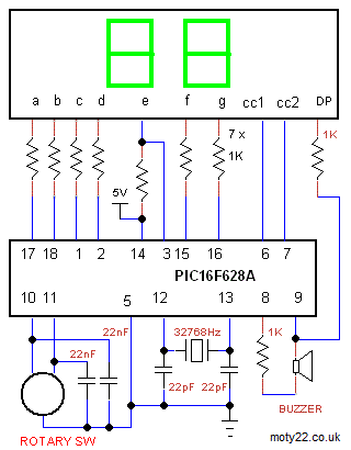
7 SEGMENT LED EGG TIMER WITH ROTARY ENCODER
Count down timer based on PIC16F628A and LED display. The CPU runs on internal 4MHz and the 32768Hz crystal is for timebase for the timer. Time span is 99 minutes. CW for increasing and CCW for decreasing the time. Decimal point flashes while counting.
When the time reaches zero the buzzer sounds for
30 seconds. To stop the buzzer turn the Rotary Encoder.
22nF caps are for switch bounce.
Buzzer is a piezo resonator.
LED are common cathode. All segments (a to g) are linked if single digits are used. The one I used is 5621AS.
Rotary Encoder is from EBAY: https://www.ebay.co.uk
OLED LED EGG TIMER WITH ROTARY ENCODER
Count down timer based on PIC16F628A and OLED display. Time span is 99 minutes. Setting the time is by the Rotary Encoder, CW for increasing and CCW for decreasing the time.
When the time reaches zero the buzzer sounds for
30 seconds. To stop the buzzer turn the Rotary Encoder.
22nF caps are for switch bounce.
OLED module is 0.96" 128x64, 4 pins connector I2C interface. Driver IC
is SSD1306.
Rotary Encoder is from EBAY: https://www.ebay.co.uk/
 
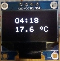
OLED EGG TIMER AND THERMOMETER
Count down timer based on PIC16F876A and OLED display
module. Included C code and circuit diagram. Time span is 100 minutes. Setting the time is by MINUTES /
SECONDS pushbuttons which advances the minutes display by 1 per second.
Holding the pushbutton counts faster. Pressing MINUTES and SECONDS
together resets the display.
Pressing START / STOP starts the countdown.
Pressing START / STOP during count pauses or restarts the counting. When the time reaches zero the buzzer sounds for
30 seconds.
DS18B20 digital sensor has temperature reading of -55 to 99.9 centigrade. The sensor doesn't require calibration. The software updates the reading every 10 seconds.
OLED module is 0.96" 128x64, 4 pins connector I2C interface. Driver IC
is SSD1306.
Circuit Description
See also Technical Tips
Pushbuttons are momentary N.O.
The buzzer, piezo buzzer is driven by a frequency of 2KHz
DS18B20 can be any type of casing.
OLED module is I2C interface, 4 pins connector. Driver SSD1306. From
ebay: https://www.ebay.co.uk/
OLED EGG TIMER WITH KEYPAD
Timer based on PIC16F628A and OLED 0.96", 128x64, SSD1306 driver. Included C code for MPLAB-X, and circuit diagram. Time span is 1 second to 99 minutes. Setting the time is by pressing 4 keys starting with tenth of minutes. * key starts the countdown, # key stops the countdown and zeros the time, to stops the alarm press any key.
Relay drive output is high from start to alarm, it can be used for driving a relay for external functions. OLED brightness can be set in the code.
Buzzer is a piezo crystal.
  
OLED EGG TIMER WITH DS18B20 THERMOMETER
Timer based on PIC16F628A and OLED 0.96", 128x64, SSD1306 driver. Included C code for MPLAB-X, and circuit diagram. Time span is 1 second to 99 minutes. Setting the time is by Min / Sec pushbuttons. To reset the time press Sec and Min simultaneously. Stop/Start button starts, pauses the countdown and stops the alarm.
Relay drive output is high from start to alarm, it can be used for driving a relay for external functions. OLED brightness can be set in the code.
Temperature sensor is DS18B20, range -55 to 99.9 centigrade.
 
EGG TIMER WITH TM1637 LED MODULE
ATtiny84
Timer based on TM1637 4 digits 7 segment module. Time span is 1 second to 99 minutes. Setting the time is by Min / Sec pushbuttons. To reset the time press Sec and Min simultaneously. Stop/Start button starts, pauses the countdown and stops the alarm.
LED brightness can be set in the code, value can be 0-7.
ATtiny can be programmed using Arduino IDE and Arduino as ISP, see Technical Tips Burning bootloader with setting "Clock Source 4MHz (external)" and Pin Mapping : "Clockwise".
 
EGG TIMER WITH TM1637 LED MODULE
PIC16F628A
Timer based on PIC16F628A and TM1637 4 digits 7 segment module. Included C code for MPLAB-X, and circuit diagram. Time span is 1 second to 99 minutes. Setting the time is by Min / Sec pushbuttons. To reset the time press Sec and Min simultaneously. Stop/Start button starts, pauses the countdown and stops the alarm.
Relay drive output is on from start to alarm, it can be used for driving a relay for external functions. LED brightness can be set in the code, value can be 0-7

LCD EGG TIMER WITH REPEAT CYCLE
Timer based on PIC16F628A LCD Module and a watch crystal. Included C code, and circuit diagram. Time span is 1 second to 99 minutes. Setting the time is by Min pushbutton which advances the minutes display by 2 per second, the Sec pushbutton advances the seconds. To reset the time press Sec and Min simultaneously.
The counting generated by the 32768Hz crystal oscillator. The CPU frequency is 4MHz from the internal oscillator.
Egg Timer: CYCLE switch open. Pressing start turns on the LED and relay and starts the countdown. When the time reaches zero the buzzer sounds for 20 seconds. After the alarm the displayed time sets to the recent time.
Repeat Timer: CYCLE switch closed. Pressing start turns on the LED and relay and starts the countdown. At end of count down LED and relay toggle and count down repeats.
Older version of software included. You are free to use the circuit diagram and the software with no
limitations.

Circuit Description
See also Technical Tips
LCD Module can be either 8 digits or 16X1 or 16X2
The buzzer is driven by a frequency of 2KHz, a piezo buzzer for that frequency will give optimal output.
The crystal is a watch crystal, refer to the data sheet for the recommended capacitors. Most crystals use 22pF-47pF.
The LED can be linked if not needed
Relay can be omitted if not needed.
The contrast pot can also blank out the display so set it if the display is dark or blank.
Pressing the Sec and Min together resets the time.
ATtiny88 LED EGG TIMER
99 minutes 7 segments LED display, Low cost Arduino Nano with ATtiny88 egg timer. Seconds and minutes are set by buttons. Also buttons for start and stop, pressing together MIN and MINx10 resets the display. Alarm at the end of count down switches on a piezo buzzer. RELAY output is high while countdown, it can be used to drive a relay.
Included ino sketch file for common cathode LED and ino file for common anode LED. When using common cathode LED colon 1K resistor is connected to 5V. When using common anode LED colon 1K resistor is connected to GRD. cc1 is the left digit. The LED I used is 5643BS-1. Brightness is set by the value of the 1K resistors, minimum value is 680R to avoid MC output max current.
ATttiny is programmed using Arduino IDE. Use these instructions https://handsontec.com/
  
ARDUINO LED EGG TIMER
99 minutes 7 segments LED display, Arduino Uno or Nano egg timer. Seconds displayed, minutes are set by buttons. Also buttons for start and stop, pressing together MIN and MINx10 resets the display. Alarm at the end of count down switches on a piezo buzzer.
The code multiplexes the 4 digits at frequency of 120Hz. 7 segment LEDs are common cathode, 4 separate digits can be used with segments a to g linked. cc1 is the digit on the right. The LEDs I used are 5621AS.

4 DIGITS LED EGG TIMER
Count down timer based on PIC16F628A and a watch crystal. Included C code and circuit diagram. Time span is 100 minutes. Setting the time is by MINUTES /
SECONDS pushbuttons which advances the minutes display by 1 per second.
Holding the pushbutton counts faster. Pressing MINUTES and SECONDS
together resets the display.
Pressing START / STOP starts the countdown.
Pressing START / STOP during count pauses or restarts the counting. When the time reaches zero the buzzer sounds for
10 seconds and the display flashes.
Download includes older version that uses low brightness LED.

Circuit Description
See also Technical Tips
The oscillator
is a watch crystal of 32.768 KHz. The 22pF can vary with different
crystal makes.
The 4 digits display is common cathode, the part I used is 5621AS. The 7 resistors of 1K enable current of
25 mA max at figure 8. The seven segments, a to g, of one digit are linked to the corresponding seven segments in the other digits.
The buzzer, piezo buzzer is driven by a frequency of
2KHz.
2 DIGITS LED EGG TIMER
Timer based on PIC16F628A and a watch crystal. Included ASM, C code, and circuit diagram. Time span is 1 to 99 minutes. Setting the time is by +MINUTE/RESET pushbutton which advances the minutes display by 1 per second, the +MINUTE X 10 pushbutton advances the tens of minutes digit. Pressing START sounds the buzzer for 0.25 sec and starts the countdown. When the time reaches zero the buzzer sounds for 20 seconds and the display flashes 'AL'. Pressing +MINUTE/RESET pushbutton resets the timer and/or stops the buzzer.

Circuit Description
See also Technical Tips
Transistors are BC337 or equivalent.
The 2 digits display is common cathode, the 7 resistors of 390 ohms enable current of 6 mA total averages at 3 mA through each segment which is on for half the time. The seven segments, a to g, of one digit are linked to the corresponding seven segments in the other digit.
The 2 digits are multiplexed by pins 17 and 18 that drive the common cathodes.
The buzzer is driven by a frequency of 1KHz, a piezo buzzer for that frequency will give optimal output. PCB for 2 Digits Timer by GAB GOB
Gabriel designed a PCB for this project using EAGLE PCB 5.9 .

|