See also USB inputs outputs without microcontroller: usb_lcd.php and ser3201.php
ANDRIOD INPUTS OUTPUTS FOR PIC16F1827
PIC16F1827 connected to Android USB via
OTG cable and UART to USB module. Controls 4 inputs, 4 outputs, and 2 analogue inputs. Switch 4 PIC outputs by the toggle
switches and read 4 inputs by the 4 lights, read voltage of 2 analogue
inputs. 10 bits analog is transmited in one byte of 7 LSB and another byte of 3 MSB. The Arduino update data every second.
The app is in free program Basic for Android (B4A) https://www.b4x.com/. Transfer APK file
to your Android device and install the app by opening the file.
USB-UART can be bought from eBay: https://www.ebay.co.uk/
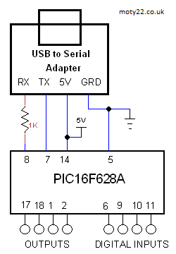
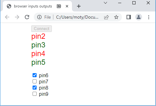
PIC16F628 INPUTS OUTPUTS FOR CHROME BROWSER
PC connects to inputs and outputs of PIC16F628A displayed on Chrome browser. PIC inputs HIGH level displayed in green and input LOW level displayed in red. HTML file includes javascript.
Browser can be Chrome, Edge and Opera browsers https://developer.chrome.com/ . Run the PIC connected to PC, open file web_io_628.html in the browser and click Connect.
USB to UART adapter can be bought from eBay: https://www.ebay.co.uk/
USB
HID WITH ANALOUE INPUTS AND DIGITL OUTPUTS
Using PIC18F2550 for connecting analogue
and digital signals to USB port . Included 4 app codes and 3 PIC codes: Visual Basic 6 code, VS2005 C++ , VB2010 code and C# codes are based on Microchip code, PIC ASM code, PIC C code for C18 and MPLABX code for XC8. Any app code works with every PIC code. The PIC microcontroller
has 10 bit analogue to digital converter. The circuit is powered
by the USB. The interface to the PC is HID class.
The inputs and outputs are updated every 10ms.
HID class (human interface device) is a class of
devices like the mouse and the keyboard, the data transfer rate
is limited to 64KB/S. The PC already has a driver for HID USB.
VB6 code includes guidance to setting up the PC.
The PC register the PID and VID (product ID) of the USB device when
it's plugged, the VB code uses these ID's to communicate with the
device. For commercial VID it is needed to buy it from USB-IF, but in your lab you can use any number.
The source code is derived from freeware from these sources: http://janaxelson.com/ , http://openprog.altervista.org/

Circuit Description
See also Technical Tips
PIC18F2550
Pins 2-5 are the analogue inputs, voltage range 0 to 5V. Max input voltage
is 5.5V . 1K resistors are to protect the PIC.
Pins 25-28 are the digital inputs, TTL voltage levels.
Pins 21-24 are the digital outputs, they can sink or source 16mA.
Pin 14 is 3.3V internal supply for the USB transceiver. 0.22uF is
required for regulation.
Pins 15,16 are the data lines to the USB connector on the PC.
Pin 20 is the PC 5V powering the PIC. It is limited to 100mA by
the PC. 0.47uF is for decoupling.
For USB wiring info: http://www.interfacebus.com/
ARDUINO INPUTS OUTPUTS FOR PC
Using PC to connect to Arduino Uno.
Included Visual Basic 6 code and arduino code. The VB6 may need an ActiveX
file downloaded from Microsoft.
The VB app connects to the Arduino via
the COM PORT that the USB drive created and connects the Arduino IDE, when
the VB app is running you cannot program the Arduino. You need to enter to
the VB app the port number in the way it is done with the IDE.
The app
displays 4 analogue inputs A0-A3, 6 digital inputs D2-D7 and 6 digital
outputs D8-D13
Code and app for PC Visual Studio 2010 can be downloaded
from GitHub:
https://github.com/ app
setup is in usb io/publish
You are free to use the Arduino code and the VB software with no
limitations.
ARDUINO INPUTS OUTPUTS FOR CHROME BROWSER
Using PC to connect to Arduino inputs and outputs. Digital inputs D2-D5 and digital
outputs D6-D9. Arduino inputs HIGH level displayed in green and input LOW level displayed in red. HTML file includes javascript.
The temperature can be displayed in Chrome, Edge and Opera browsers https://developer.chrome.com/ . Run the Arduino connected to PC, open file web_io.html in the browser and click Connect.
You are free to use the Arduino code and the VB software with no
limitations.
ARDUINO INPUTS OUTPUTS FOR ANDROID USB
Arduino connected to Android USB via
OTG cable, controls 4 inputs, 4 outputs, analogue inputs and temperature
sensor DS21B20. Switch 4 Arduino outputs by the toggle
switches and read 4 inputs by the 4 lights, read voltage of 2 analogue
inputs. The Arduino update data every second.
The app is in free program Basic for Android (B4A) https://www.b4x.com/. Transfer APK file
to your Android device and install the app by opening the file.
ARDUINO INPUTS OUTPUTS FOR ANDROID
BLUETOOTH
Arduino connected to Android USB via
HC-05 Bluetooth module, controls 4 inputs, 4 outputs, analogue inputs,
temperature sensor and analogue output (PWM). Switch 4 Arduino outputs by the toggle
switches and read 4 inputs by the 4 lights, read voltage of 2 analogue
inputs. The Arduino update data every second.
The app is in free program Basic for Android (B4A) https://www.b4x.com/. Transfer APK file
to your Android device and install the app by opening the file.
Circuit Description
See also Technical Tips
4K7 is a pullup for DS18B20
1K is to reduce the 5V
output of Arduino to 3.3V RX input of the HC-05.
HC-05 is not used in
USB interface, connect Arduino to Android device using OTG cable.
All
inputs or outputs are optional. |